Introduction: The Capex Milestone That Defines Production Scalability
In the lifecycle of a new small domestic appliance—whether an innovative visual-window air fryer, a high-torque planetary mixer, or an ergonomic car vacuum—the transition from digital CAD files to physical steel tooling represents the most capital-intensive and risk-heavy phase of the entire development program. Cutting steel for injection molds requires significant capital investments and commits the brand to hard lead times.
A minor oversight in wall thickness transitions, parting line geometry, or cooling channel placement can introduce permanent defects: sink marks, warpage, flash, or prolonged injection cycle times that erode unit margins over hundreds of thousands of production units.
For brand owners and product managers evaluating custom OEM/ODM development, understanding the structural progression of mold tooling is essential for maintaining schedule discipline, cost predictability, and dimensional precision.
+---------------------------------------------------------------------------------------------------+
|                        OEM/ODM TOOLING & PRODUCTION DEVELOPMENT ROADMAP                           |
+--------------------------+------------------------------------+-----------------------------------+
| Milestone Phase          | Key Engineering Deliverables       | Critical Verification Gates       |
+--------------------------+------------------------------------+-----------------------------------+
| 1. ID & MD Conception    | 3D surface modeling, internal guts | CMF sign-off, internal layout     |
| 2. DFM & Mold Flow       | Draft angles, gating, sink risk    | Wall uniformity, cooling analysis |
| 3. Steel Sourcing & CNC  | Mold base, cavity & core machining | H13/718H steel hardness certs     |
| 4. EDM & Bench Fitting   | Spark erosion for deep ribs, polish| Core-to-cavity alignment & seal   |
| 5. T0 & T1 Sample Trials | First raw plastic part ejection    | CMM dimension scan vs. 3D CAD     |
| 6. Tuning & Texture      | Mold modifications, SPI/VDI finish | Cosmetic defect sign-off (Zero-fl)|
| 7. Production Ramp (SOP) | Pilot run, multi-cavity balancing  | CPK study, assembly cycle timing  |
+--------------------------+------------------------------------+-----------------------------------+
Phase 1: Industrial Design (ID) Refinement and Mechanical Engineering (MD) Architecture
The tooling journey begins by translating consumer ergonomics and styling concepts into functional mechanical architecture:
- Internal Mechanical Packaging: Mechanical engineers position key functional sub-assemblies: electric motors, drive shafts, heating coils, PCBs, and centrifugal cooling fans. Clearance tolerances must account for thermal expansion, dynamic mechanical vibration, and internal airflow cooling.
- Component Partitioning: The industrial design housing is deconstructed into moldable plastic and structural metal parts. Parting lines are strategically located along natural seams to ensure parting lines remain hidden from the consumer’s primary line of sight.
Phase 2: Design for Manufacturability (DFM) and Advanced Mold Flow Simulation
Before tool steel procurement begins, comprehensive Design for Manufacturability (DFM) audits and computerized Mold Flow simulations take place. As established in precision manufacturing engineering protocols, such as Midwest Mold’s Plastic Injection Tooling Guide, an exhaustive DFM phase prevents expensive tooling modifications later in the schedule.
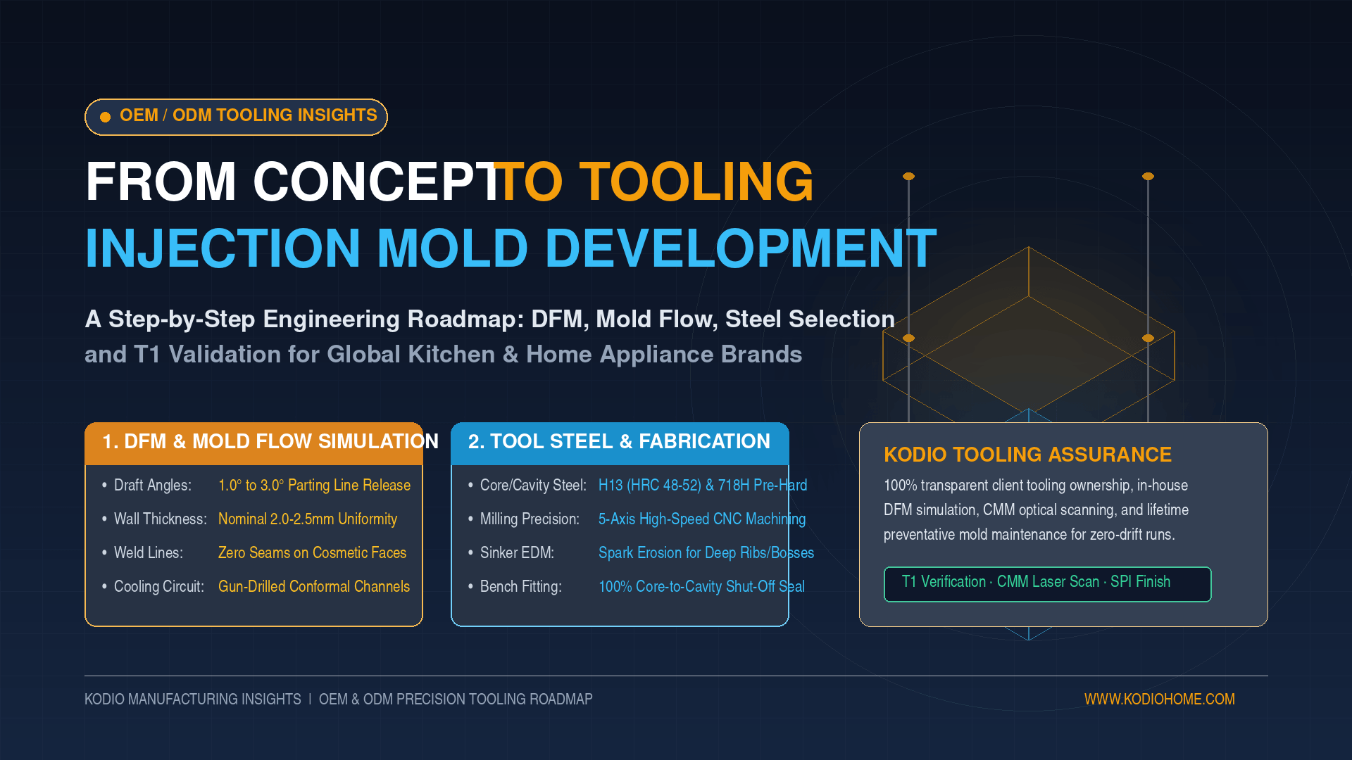
- Draft Angle Optimization: Vertical surfaces require draft angles (typically 1.0° to 1.5° for smooth finishes, and upwards of 3.0° to 5.0° for heavy VDI leatherette or matte textures) to enable parts to release cleanly from the mold core without drag marks.
- Wall Thickness Uniformity: Countertop appliances frequently require high-impact ABS, flame-retardant polypropylene (PP), or high-temp polycarbonate (PC). Uneven wall thicknesses trigger uneven volumetric shrinkage, producing sunken sink marks over structural ribs or warped side panels. DFM enforces uniform nominal walls (2.0 mm to 2.5 mm) with coring techniques on thicker boss sections.
- Gate Placement and Weld Line Elimination: Mold Fflowsimulation models polymer melt flow front velocities, shear rates, and clamp tonnage requirements. Engineers strategically position hot runner or cold runner injection gates to ensure weld lines (where two flow fronts meet) do not form across high-stress structural mounting bosses or prominent aesthetic front faces.
Phase 3: Mold Base Fabrication, Core/Cavity Steel Selection, and CNC Machining
The operational longevity of a mold tool depends on the grade of steel selected for the core and cavity inserts:
- Tool Steel Selection:
- Standard Production (P20 Steel / 1.2311): Hardened to HRC 28–32; suitable for budget programs or low-wear cosmetic parts with lifespans up to 300,000 shots.
- High-Wear & Textured Parts (718H / NAK80): Pre-hardened to HRC 36–40; provides superior polishability for high-gloss finishes and resists abrasive wear.
- High-Volume & Glass-Filled Polymers (H13 Steel / 1.2344): Vacuum heat-treated to HRC 48–52; imperative for abrasive glass-reinforced nylon motor brackets, blender blade housings, and parts exceeding 1,000,000 production cycles.
- High-Speed CNC Milling and Gun Drilling: Mold bases undergo precision high-speed 5-axis CNC roughing and finishing. Conformal cooling channels are gun-drilled through the core and cavity blocks to optimize heat dissipation, reducing molding cycle times by 15% to 30%.
Phase 4: Electrical Discharge Machining (EDM) and Precision Bench Fitting
Certain appliance features—such as deep, narrow structural snap-fit ribs, internal screw bosses, and intricate air vent louvers—cannot be cut by rotary CNC endmills:
- Sinker EDM (Spark Erosion): High-purity copper or graphite electrodes are machined to precise inverse geometries. Immersed in dielectric fluid, electrical discharges erode the hardened steel to form sharp, deep features with micron-level accuracy.
- Bench Fitting and Mold Assembly: Master toolmakers hand-fit ejector pins, slide actions, angle lifters, and hydraulic pull cores. Mating surfaces are spotted with engineer’s blue to verify 100% sealing shut-off along parting lines, preventing high-pressure polymer injection flash.
Phase 5: The Validation Lifecycle: T0, T1, and T2 Sample Runs
Once tool assembly is complete, the mold is mounted into an injection molding machine for initial sample trials:
- T0 Trial (Dry Function Run): Verifies mold mechanical actions—ensuring slides, lifters, hot runner manifolds, and ejector return pins cycle smoothly without mechanical binding.
- T1 Trial (First Injection Samples): Injected with standard production resins at baseline temperature and pressure profiles. T1 samples are rarely cosmetically complete; their primary purpose is dimensional verification.
- Coordinate Measuring Machine (CMM) Dimensional Verification: High-precision CMM probes and 3D optical laser scanners measure molded parts against 3D CAD step files. Critical dimensions, screw boss alignments, and clip clearances are checked for plastic shrinkage compensation.
- T2 Tuning & Texture Application: Toolmakers modify steel dimensions (steel-safe adjustments), fine-tune gate sizes, re-balance multi-cavity runners, and apply final surface texturing via chemical acid etching or laser texturing to SPI (Society of the Plastics Industry) or VDI 3400 standards.
Kodio’s Tooling Competence: Speed, Ownership, and Lifetime Tooling Maintenance
At Kodio, mold tooling is managed as an integrated engineering discipline to minimize time-to-market while safeguarding client investments:
- Transparent Tooling Ownership: Unlike traders or contract assemblers that retain proprietary hold over mold designs, Kodio guarantees complete, unambiguous tooling ownership for OEM/ODM brand partners. Full 2D/3D mold layouts, electrode designs, and CNC tool paths are documented and accessible.
- In-House DFM and Prototyping: Kodio’s engineering team executes internal DFM reviews and functional SLS/SLA 3D-printed prototypes before steel fabrication begins. This discipline resolves cosmetic, structural, and tooling defects prior to capex expenditure.
- Lifetime Tooling Maintenance Program: Molds operating within Kodio’s manufacturing facilities undergo strict preventative maintenance schedules: ultrasonic cleaning of cooling circuits, lubrication of guide pillars every 10,000 cycles, and cavity surface protection to guarantee the tool reaches its rated shot life without dimensional drift.
Procurement Takeaway: During the tooling design stage, an appliance program’s success is guaranteed. You may safeguard your capital investment and avoid launch delays by working with a manufacturer that integrates transparent trial verification, proper tool steel selection, and internal DFM simulation.